|
|
|
Who's Online
There currently are 6043 guests online. |
|
Categories
|
|
Information
|
|
Featured Product
|
|
|
 |
|
|
There are currently no product reviews.
 ;
El producto satisface las necesidades del servicio t
;
This is a good quality scan of the Operation & Maintenance (Service) Manual for the PAL version of this high-band broadcast umatic, BVU-800P
All schematics and lineup procedures appear to be included in this one manual AFAICT.
The file size is just over 113 MB which gives an idea of the quality and number of pages.
All of the schematics, which contain some fairly small print, are easily readable when you zoom into the page.
John Thompson, Newcastle Upon Tyne, England.
;
Good quality, all schematics of few of models. There is also short form of user manual and regulation manual.
;
Perfect copy of the service manual. you can enlarge every page, and it comes up
with all details.
;
It´s very very nice manual with all, what i need. Original in good quality. Very fast business. Very much thanks...
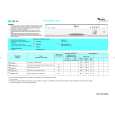
HTP-940 ADJUSTMENT PROCEDURE
SKW-940 : POWERED SUBWOOFER / ADJUSTMENT OF IDLING CURRENT
[When] 1. Exchange transistors (Q505 - Q519). 2. Exchange MAIN PC board ass'y (NAAF-8829). [Procedure] <Note> No speaker load and No input signal. 1. Short test point P631 for amplifier is under active mode. 2. Adjust the trimming resistor R544 so that the reading of multimeter becomes 52 ohm to 53 ohm. 3. Connect the DC voltmeter to test point P531. <Fig-1> 4. Connect the AC power cord into a wall outlet. 5. Press POWER button to turn on the unit. (MPP type only) 6. Confirm the voltage of above point after 6 minutes to 8 minutes. (Heat running) 7. When less than 3.20 mV : Readjust the trimming resistor above so that the voltage becomes 4.5 mV to 5.0 mV. When 3.30 mV to 5.20 mV : Not necessary to adjust. When 5.21 mV to 10.0 mV : Readjust the trimming resistor above so that the voltage becomes 5.0 mV to 5.5 mV. When 10.1 mV to 20.0 mV : Readjust the trimming resistor above so that the voltage becomes 5.6 mV to 6.0 mV. 8. Press POWER button to turn off the unit. (MPP type only) 9. Disconnect the DC voltmeter. 10. Disconnect the AC power cord from a wall outlet.
100 ohm (1/4W) DC voltmeter
<Fig-1>
Test point
Trimming resistor
Test point
R544
P531
P531
MAIN PC board ass'y "NAAF-8829"
Test point
P631
Short
|
|
|
> |
|