|
|
|
Who's Online
There currently are 5714 guests online. |
|
Categories
|
|
Information
|
|
Featured Product
|
|
|
 |
|
|
There are currently no product reviews.
 ;
MACKIE HR824 26 pages English-only Service Manual contains:
1) HR824 technical overview with the description of front and rear panel switches.
2) HR824 specs
3) Block Diagram
4) Wiring Diagram
5) Packaging management
6) Spare part & final assembly list (for PCB rev A and B) + exploded view
7) Test Procedures (where, how to measure voltage...) including Test Point diagram on the PCB.
8) IC and Transistor charts.
Excellent guide: very clear, good scan quality enabling us to print readable diagram :-)
Note:
Mackie HR824 make extensive use of surface mount devices (SMD). Service on the HR824 must
only be undertaken by experienced service technicians with the right tools, experience and patience to perform surface mount rework when needed.
;
This Service manual is very well scanned and its clean to read, no any anti-theft words that un-english could understand. I got my CCD600 working with this manual and it´s clear shematics :)
;
I was very pleased with the service provided and was surprised at how good the quality was of the manual. I thought it may be a third generation copy or so, but it is as good as the websites that charge 3 times this much. I repair some electronics for family and friends without charge, so this is perfect for me. Thank you very much.
;
The service was great and the document was also great. Highly recommend!!!!
If anyone has a users manual... Please email me. need one. $ [email protected]
;
I needed a service manual as the display on my oscilloscope was very dim. I thought I'd give owner-manuals.com a try, as they advertised a huge number of manuals. Sure enough they had one listed. I bought it hoping it would be useful... actually, I bought it hoping it would be readable! I've had manuals from online sources in the past, and been very disappointed. Not this time! An excellent manual, complete, and very readable. Using it I fixed my 'scope, and as such the manual was an investment that paid off manyfold. Do I have any complaints? One very minor one - The circuit diagrams could have been scanned at a higher resolution, as some of the details were a little difficult to make out - not impossible, just not as easy as my old eyes would like! Overall, I'm very satisfied with my manual, and I will certainly be using this company again. Well done.
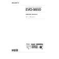
TX-2100 ADJUSTMENT AND CONFIRMATION PROCEDURES 1
Idling current adjustment Before Idling adjustment, turn the trimming resistors R533 and R534 to counter clockwise. Connect the DC voltmeter to terminals P521 and P522. After turn POWER to ON, adjust the trimming resistors R533 and R534 so that the reading of voltmeter becomes 2.0 mV. After adjustment, attach the top cover. Confirm the voltage of points above after about five minutes. When less than 7.0 mV, readjust the resistors above so that the voltage becomes 7.0 mV. When 7.0 mV to 9.0 mV, you are not necessary to adjust. When more than 9.0 mV, readjust the resistors above so that the voltage becomes 9.0 mV.
RIGHT VCT
NCAR-5864
P211a
P613a
P522
R534
R533 L-IID 30 P711a 1
IID
IID
VCT P521 LEFT
Confirmation of protection circuit 1. Confirmation of operation of speaker relay Confirm that the speaker relays turn ON approximate. 5 seconds after the power switch is turned ON. Confirm that the speaker relays turn OFF immediately after the power switch is turned OFF. 2. Confirmation of DC detection circuit Press and hold down CD button, then press DIRECT TUNING button. After "TEST- " on the FL tube light on, press TAPE 1 button to set the unit to "TEST-1 00". Apply DC 1.5 to 3V to CD terminal with no load. Confirm that the speaker relay turns OFF. Apply DC -1.5 to -3V to CD terminal with no load. Confirm that the speaker relay turns OFF. Caution: Don't apply DC voltage more than 1 sec..
JL912a
JL913a
|
|
|
> |
|