|
|
|
Who's Online
There currently are 5558 guests online. |
|
Categories
|
|
Information
|
|
Featured Product
|
|
|
 |
|
|
There are currently no product reviews.
 ;
MACKIE HR824 26 pages English-only Service Manual contains:
1) HR824 technical overview with the description of front and rear panel switches.
2) HR824 specs
3) Block Diagram
4) Wiring Diagram
5) Packaging management
6) Spare part & final assembly list (for PCB rev A and B) + exploded view
7) Test Procedures (where, how to measure voltage...) including Test Point diagram on the PCB.
8) IC and Transistor charts.
Excellent guide: very clear, good scan quality enabling us to print readable diagram :-)
Note:
Mackie HR824 make extensive use of surface mount devices (SMD). Service on the HR824 must
only be undertaken by experienced service technicians with the right tools, experience and patience to perform surface mount rework when needed.
;
This Service manual is very well scanned and its clean to read, no any anti-theft words that un-english could understand. I got my CCD600 working with this manual and it´s clear shematics :)
;
I was very pleased with the service provided and was surprised at how good the quality was of the manual. I thought it may be a third generation copy or so, but it is as good as the websites that charge 3 times this much. I repair some electronics for family and friends without charge, so this is perfect for me. Thank you very much.
;
The service was great and the document was also great. Highly recommend!!!!
If anyone has a users manual... Please email me. need one. $ [email protected]
;
I needed a service manual as the display on my oscilloscope was very dim. I thought I'd give owner-manuals.com a try, as they advertised a huge number of manuals. Sure enough they had one listed. I bought it hoping it would be useful... actually, I bought it hoping it would be readable! I've had manuals from online sources in the past, and been very disappointed. Not this time! An excellent manual, complete, and very readable. Using it I fixed my 'scope, and as such the manual was an investment that paid off manyfold. Do I have any complaints? One very minor one - The circuit diagrams could have been scanned at a higher resolution, as some of the details were a little difficult to make out - not impossible, just not as easy as my old eyes would like! Overall, I'm very satisfied with my manual, and I will certainly be using this company again. Well done.
TX-SR55 IC BLOCK DIAGRAMS AND TERMINAL DESCRIPTIONS
IC42S16100 (16-Mbit Synchronous Dynamic RAM)
TERMINAL DESCRIPTION
Pin No. 20 to 24 27 to 32 Pin name A0-A10 Function A0 to A10 are address inputs. A0-A10 are used as row address inputs during active command input and A0-A7 as column address inputs during read or write command input. A10 is also used to determine the precharge mode during other commands. If A10 is LOW during precharge command, the bank selected by A11 is precharged, but if A10 is HIGH, both banks will be precharged. When A10 is HIGH in read or write command cycle, the precharge starts automatically after the burst access. These signals become part of the OP CODE during mode register set command input. A11 is the bank selection signal. When A11 is LOW, bank 0 is selected and when high, bank 1 is selected. This signal becomes part of the OP CODE during mode register set command input. CAS, in conjunction with the RAS and WE, forms the device command. See the "Command Truth Table" item for details on device commands. The CKE input determines whether the CLK input is enabled within the device. When is CKE HIGH, the next rising edge of the CLK signal will be valid, and when LOW, invalid. When CKE is LOW, the device will be in either the power-down mode, the clock suspend mode, or the self refresh mode. The CKE is an asynchronous input. CLK is the master clock input for this device. Except for CKE, all inputs to this device are acquired in synchronization with the rising edge of this pin. The CS input determines whether command input is enabled within the device. Command input is enabled when CS is LOW, and disabled with CS is HIGH. The device remains in the previous state when CS is HIGH. I/O0 to I/O15 are I/O pins. I/O through these pins can be controlled in byte units using the LDQM and UDQM pins.
19 16 34
A11 CAS CKE
35 18
CLK CS
2, 3, 5, 6, 8, 9, 11, 12, 39, 40, 42, 43, 45, 46, 48, 49 14, 36
I/O0 to I/O15 LDQM, UDQM
LDQM and UDQM control the lower and upper bytes of the I/O buffers. In read mode, LDQM and UDQM control the output buffer. When LDQM or UDQM is LOW, the corresponding buffer byte is enabled, and when HIGH, disabled. The outputs go to theHIGH impedance state when LDQM/UDQM is HIGH. This function corresponds to OE in conventional DRAMs. In write mode, LDQM and UDQM control the input buffer. When LDQM or UDQM is LOW, the corresponding buffer byte is enabled, and data can be written to the device. When LDQM or UDQM is HIGH, input data is masked and cannot be written to the device. RAS, in conjunction with CAS and WE, forms the device command. See the "Command Truth Table" item for details on device commands. WE, in conjunction with RAS and CAS, forms the device command. See the "Command Truth Table" item for details on device commands. VCCQ is the output buffer power supply. VCC is the device internal power supply. GNDQ is the output buffer ground. GND is the device internal ground.
17 15 7, 13, 38, 44 1, 25 4, 10, 41, 47 26, 50
RAS WE VCCQ VCC GNDQ GND
 $4.99 TXSR55 ONKYO
Owner's Manual Complete owner's manual in digital format. The manual will be available for download as PDF file aft… 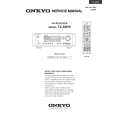 $4.99 TX-SR55 ONKYO
Parts Catalog Parts Catalog only. It's available in PDF format. Useful, if Your equipment is broken and You need t…
|
|
|
> |
|